

Product Selection Guide
A practical route from interface requirement to material family — how to pick the right MIWAKEE thermal interface material across sheets and pastes, plus packaging, storage and application guidance for your target system.
From Interface Requirement to Material Family
Begin by determining whether the design requires gap filling or direct contact-interface treatment — then review the matching families below.
Interface Filling
- Begin by determining whether the design requires gap filling or direct contact-interface treatment.
- Sheet-format solutions → review the MTP thermal pad family and the MTC / MTCK thermal insulation families.
- Paste-format solutions → review thermal grease, one- or two-component gap filler or potting compound according to the design and process.
Sheet-Format Selection
- MTP thermal pads — the MIWAKEE selection chart lists 1.0–15.0 W/(m·K).
- MTP silicone-free grades — 2.0–5.0 W/(m·K).
- MTC / MTCK thermal insulators — select by thermal conductivity, substrate type, tack and required sheet construction.
Paste-Format Selection
- Thermally conductive potting encapsulate — 1.0–4.0 W/(m·K), identified for applications requiring circuit protection.
- MWK 2K gap filler — two-component liquid gap filler options; the N-series family lists 1.0–10.0 W/(m·K), with chart ranges of 1.2–10.0 W/(m·K) (2K) and 1.0–15.0 W/(m·K) (1K).
- Thermal grease — contact-interface filling where the design and assembly process support paste application.
Circuit Protection & Substrate
Where circuit protection is required, the MWK selection chart directs the user to thermally conductive potting encapsulate. For insulation sheets, review the tack requirement and substrate:
- The chart identifies PI film and fiberglass options, as well as the MTC and MTCK families.
- Match sheet construction to the assembly: die-cut parts, rolls or standard sheet.

MWK TIM Selection Route
The main selection route from the supplied guide — start from the design, branch by interface role, then narrow by format and component count.
Paste Materials & Thermal Insulation Sheets
Two decision paths from the selection guide — paste materials routed by circuit-protection need and component count, insulation sheets routed by tack and substrate.
Paste Material: Circuit Protection & Components
Thermal Insulator: Tack & Substrate
Note — family-level values shown in the diagrams are selection guidance only; the exact grade range is defined by the current product data sheet. Confirm the model-specific TDS before release.
Customized Service & Engineering Support
Standardized products may not match every system-level requirement — customization addresses the actual interface, assembly process and operating conditions, not thermal conductivity in isolation.
Material construction
Low-modulus polymer; silicone or silicone-free formulation; fiberglass-reinforced, film-reinforced, rubber-based or non-reinforced structures.
Thermal & mechanical properties
Selected thermal conductivity, hardness, softness, compression behaviour, resilience, density, wear resistance and bonding strength.
Surface & interface characteristics
Single- or double-sided tack, low oil separation, low volatility and controlled adhesion.
Product format
Sheets, rolls, custom die-cut parts, ultra-thin sections and specified thicknesses.
Manufacturing integration
Automated installation and dispensing solutions, process-compatible material formats and application support.
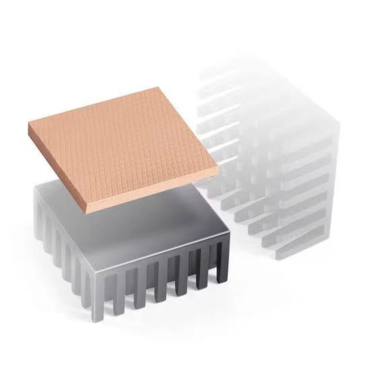
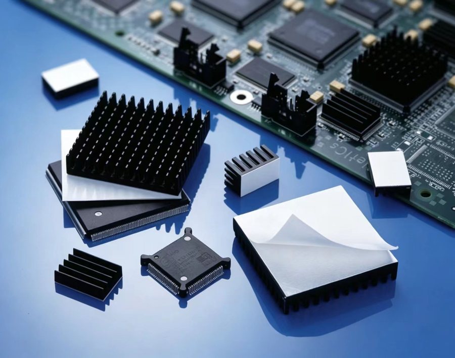
Application-specific development
Project & production benefits
- Supports innovative project design and improves design flexibility.
- Improves production and assembly efficiency.
- Supports consistent assembly quality and product reliability.
- Improves product, personnel and operational safety.
- Energy-saving & environmental protection in line with ISO 14001 principles.
- Reduces assembly and testing costs — stronger project competitiveness.
Packaging, Storage & Handling
Packaging formats and shelf life per family, the package-size matrix, and the handling rules to keep material in spec.
MWK product packaging
| Product family | Packaging / shipment | Shelf life |
|---|---|---|
| 2K gap filler | 50 ml AB (25 ml each); 300 ml AB (300 ml per A/B — verify package configuration); 400 ml AB (200 ml each); 30 kg AB (10 kg each). | 6 months at 25 °C / 50% RH, original packaging |
| Potting | 1 kg can; 5 kg can; 20 kg pail. | 12 months |
| 1K gap filler | 30 ml, 50 ml and 300 ml cartridges; 5 kg can; 20 kg pail. | 6 months before opening |
| Thermal grease | 30 ml PE cartridge; 1 kg can; 2 kg can; 10 kg pail. | 6 months |
| MTC / MTCK insulator | Roll or die-cutting part. | — |
| MTP pads & PCM | Standard sheet 300 mm × 400 mm; custom die-cut parts available. Thickness increments of 0.25 mm for listed sheet products. | — |
Package size matrix
| Package size | Potting series | 2K GF series | 1K GF series | Grease series |
|---|---|---|---|---|
| 50 cc | Listed | Listed | Listed | — |
| 400 cc | — | Listed | — | — |
| 2600 cc | Listed | Listed | — | — |
| 20 kg | Listed | Listed | Listed | — |
| Thermal grease | — | — | — | 1 kg / 10 kg listed |
Storage & handling
- Store liquid gap fillers in their original sealed containers at or below 25 °C and 50% RH unless the data sheet states otherwise.
- Store syringe containers and test tubes with the nozzle end facing down unless otherwise specified.
- Store potting compounds and dispensable materials in a cool, dry, ventilated place, following product-specific shelf-life instructions.
- PCM materials: store below 40 °C, protected from compression and direct sunlight.
- Clean mating surfaces before applying dispensable materials; seal unused material promptly after use.
Thermal Management Across Electronic & Industrial Systems
Where the material families are used, and which format fits the need — from preformed pads for repeatable assembly to dispensable fillers for complex topography.


| Application area | Representative applications |
|---|---|
| Automotive electronics | ECUs; OBC transformers and PFC; DC/DC converters; battery packs and cooling plates; motor control; vehicle-mounted radar; automotive sensors; power semiconductor modules. |
| Network & telecommunications | Routers; Wi-Fi and VoIP equipment; network communication modules; high-speed storage drives; 5G base stations; optical modules; RFID systems. |
| Computing & data systems | CPU and GPU cooling; ASICs and DSPs; VRMs; BGA modules; notebooks and desktop computers; servers; storage modules; hard drives; SSDs; scanners and printers. |
| Consumer electronics | Gaming systems; flat-panel displays; LCD backlights; DVD players; portable devices; LED lighting. |
| Power & industrial equipment | Power supplies; power converters; LEDs; automation equipment; high-voltage applications; power modules; heat pipes; industrial control systems. |
| Security & imaging | CCTV and security equipment; precision optical equipment; medical equipment; sensors and control units. |
| Mechanical interfaces | Between ICs and heat sinks or chassis; between cooling devices and frames; between battery packs and cooling plates; within graphics-card cooling modules. |
Material formats by application need
- Preformed pads & die-cut sheets — defined gaps and repeatable assembly.
- Dispensable 1K / 2K gap fillers — variable gaps, complex topography, automated application.
- Thermal grease — thin bond lines and controlled-pressure contact interfaces.
- Electrically insulating thermal sheets — power modules and semiconductor interfaces.
- Potting compounds — encapsulation and circuit protection.
- Phase-change materials — temperature-activated wetting and conformity.
- EMI absorber pads — where thermal transfer and electromagnetic absorption are needed together.
Not sure which material fits your heat path?
Send the heat load, gap and environmental class — our application engineers will recommend the material and format for that position.