

\n
\n
\n
\n \n

Automotive
Material
Solutions

\n \n

Thermal, structural and protective materials for
EV, LSEV and hybrid vehicle platforms

\n

One qualified platform for the four systems that define an electric vehicle — battery pack, e-motor, battery management system and on-board charger. From cell-to-cooling interface to potting, sealing and dielectric protection.

\n \n
\n
\n
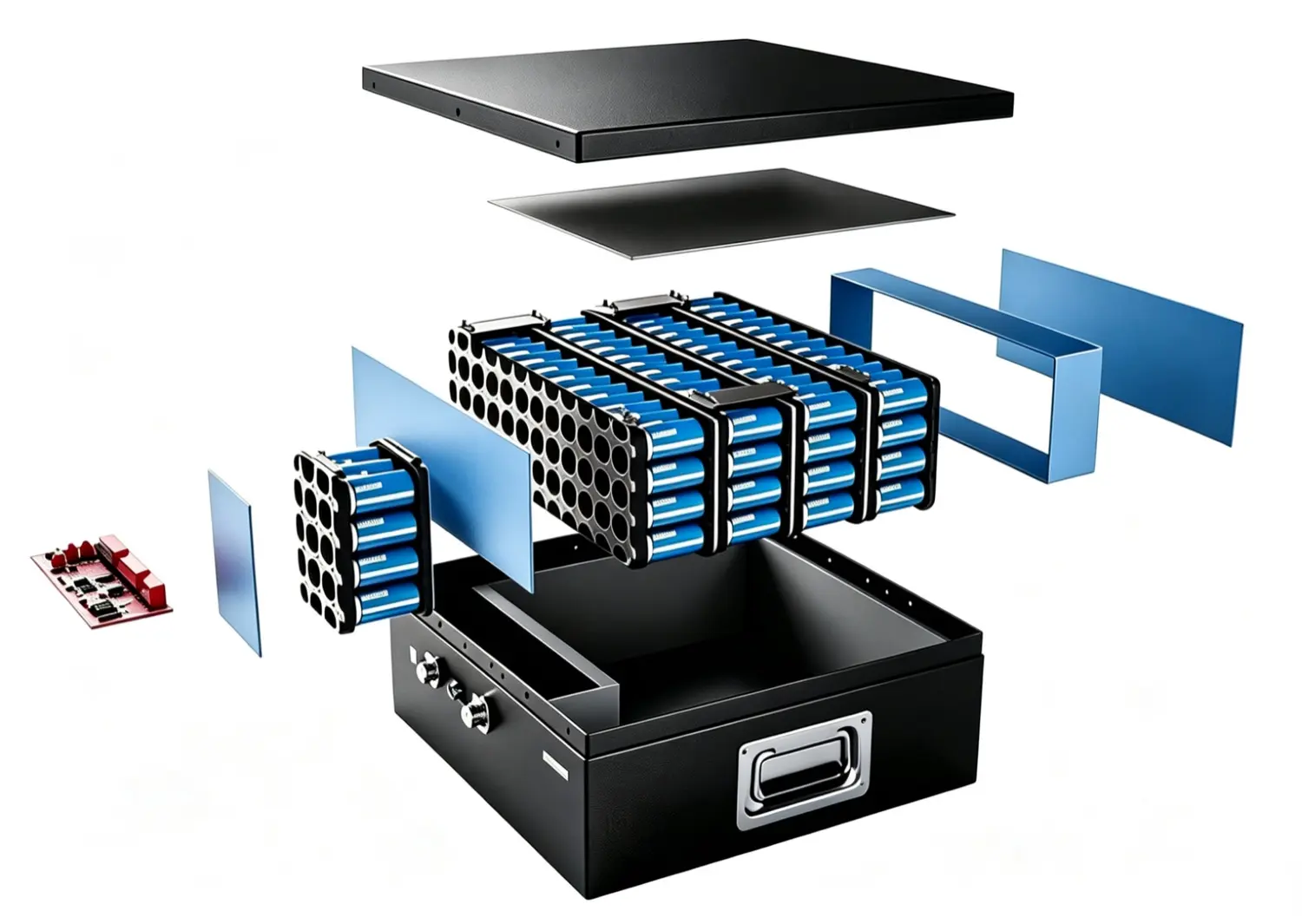
\n Exploded view of an EV battery pack with cylindrical cells, modules, cooling plate and enclosure\n
\n
\n
\n
\n
\n
\n
\n
\n
Battery Pack
Cell, module and pack interfaces
\n
E-Motor
Rotor, stator and housing
\n
BMS
Chip, MOSFET and PCB cooling
\n
OBC
Chip, magnetics and power stage
\n
\n
\n
\n
\n
\n
\n
\n System Overview\n

Four Systems Define the Automotive Material Brief

\n
\n

Each system has its own interfaces, gap tolerances and thermal targets — the same material platform is specified differently in each one.

\n
\n
\n
\n 01\n

Battery Pack

\n
  • Thermal management
  • Cell performance
  • Sealing and assembly adhesives
\n Battery solutions \n
\n
\n 02\n

E-Motor

\n
  • Rotor fixing and bonding
  • Stator thermal potting
  • Housing and fan assembly
\n E-motor solutions \n
\n
\n 03\n

BMS

\n
  • Chip and heatsink interface
  • PCB to heatsink
  • MOSFET insulation and cooling
\n BMS solutions \n
\n
\n 04\n

OBC

\n
  • Chip thermal interface
  • Transformer and capacitor potting
  • MOSFET insulation
\n OBC solutions \n
\n
\n
\n
\n
\n
\n
\n
\n 01 / Battery Solutions\n

Battery Pack, Module and Cell Interfaces

\n
\n

Seven interface families cover the thermal path, cell performance, BMS protection, sealing, insulation, bonding and the enclosure.

\n
\n
\n
\n EV battery pack exploded view showing cells, module frames, cooling plate and enclosure\n
Battery pack — cell, module and pack level
\n
\n
\n
    \n
  • \n
    Thermal Management
    \n
    Gap PadGap FillerThermally Conductive Potting
    \n
  • \n
  • \n
    Cell Performance
    \n
    Dielectric CoatingConductive Electrode Coating
    \n
  • \n
  • \n
    PCB & BMS
    \n
    PCB ProtectionThermal Management
    \n
  • \n
  • \n
    Battery Assembly Adhesives
    \n
    Structural AdhesivesThermally Conductive Adhesives
    \n
  • \n
  • \n
    Sealing
    \n
    Thread LockersGasketing
    \n
  • \n
  • \n
    PC SheetsElectrical insulation
    \n
    0.175–0.5 mmOne-side PSA tape
    \n
  • \n
  • \n
    Casing Solutions
    \n
    ImpregnationMetal PretreatmentFire Protective Coatings
    \n
  • \n
\n

Material format, thickness and compression are set per interface — pads where the gap is defined, fillers where it is not.

\n
\n
\n
\n
\n
\n
\n
\n
\n 02 / E-Motor Solutions\n

Rotor, Stator and Motor Housing

\n
\n

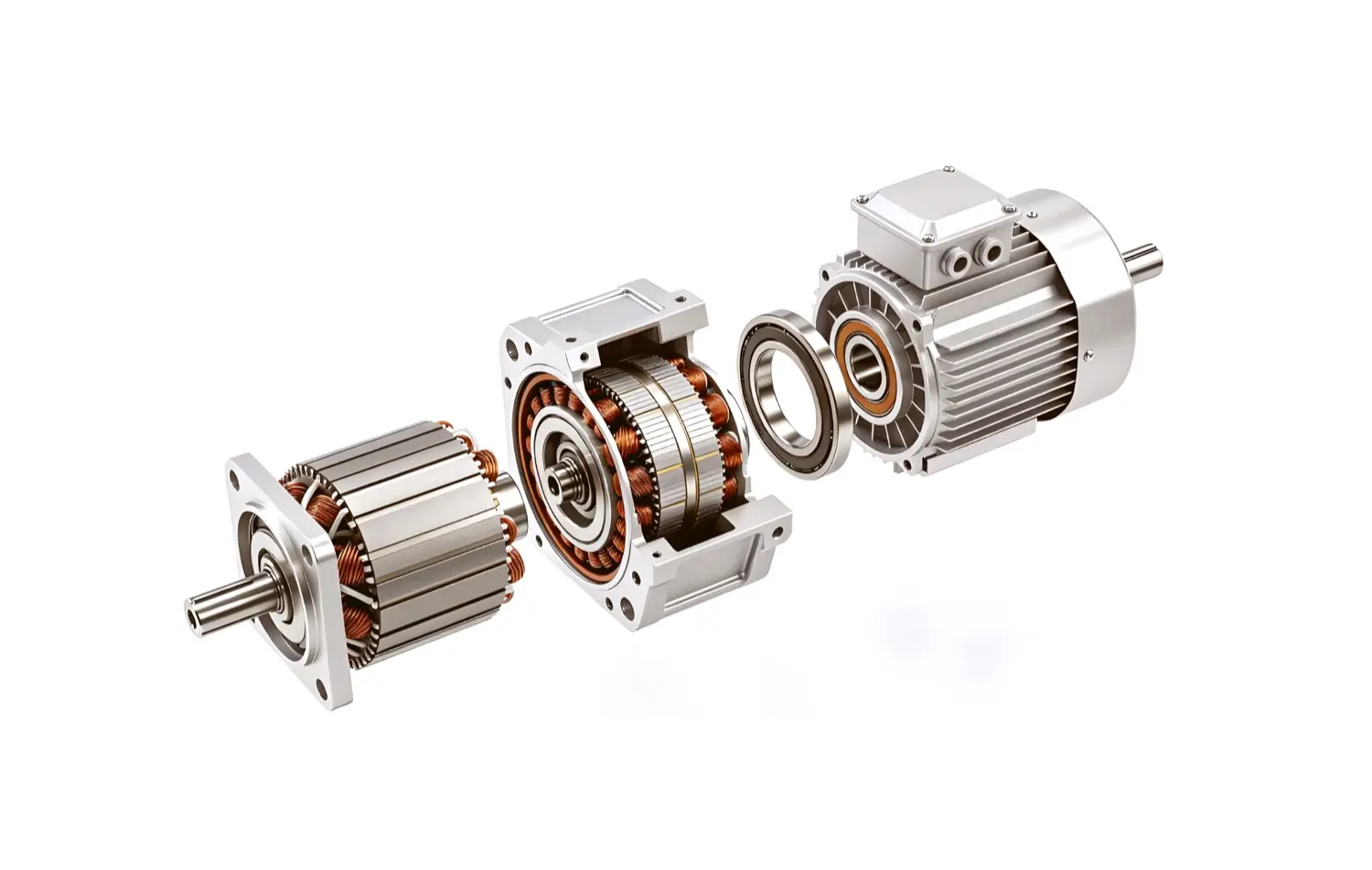
Structural bonding holds the rotor together; thermal potting moves heat out of the stator and protects the housing.

\n
\n
\n
\n Exploded view of an electric motor with rotor, stator windings, bearings and housing\n
E-motor — rotor, stator and housing
\n
\n
\n
    \n
  • \n
    Motor RotorFixing & bonding
    \n
    Epoxy Structural AdhesivesPU Structural AdhesivesAnaerobic Adhesives
    \n
  • \n
  • \n
    Motor StatorThermal
    \n
    Silicone Potting CompoundEpoxy Potting Compound
    \n
  • \n
  • \n
    Fan Housing & Mounting Base
    \n
    Modified Epoxy AdhesivesSilicone RTV Adhesives
    \n
  • \n
  • \n
    Motor Housing
    \n
    Silicone Thermal PottingEpoxy PottingPU Thermal Potting
    \n
  • \n
\n

Potting compound choice follows the thermal class and the CTE of the neighbouring metals, not only the conductivity figure.

\n
\n
\n
\n
\n
\n
\n
\n
\n 03 / BMS Solutions\n

Battery Management Electronics

\n
\n

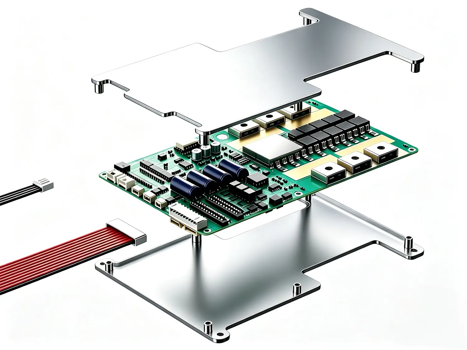
Interface materials for chip-to-heatsink, PCB-to-heatsink and MOSFET cooling inside the BMS enclosure.

\n
\n
\n
\n Exploded view of a BMS control board between aluminium heatsinks with connectors and busbars\n
BMS — chip, PCB and MOSFET cooling
\n
\n
\n
    \n
  • \n
    Chip & Heatsink
    \n
    2K Gap FillerSoft Thermal Gap PadThermal Grease
    \n
  • \n
  • \n
    PCB & Heatsink
    \n
    Reinforced Thermal PadSilicone RTV Adhesives
    \n
  • \n
  • \n
    MOSFET & PCB / MOSFET & Heatsink
    \n
    High Performance Silpad2K Gap Filler
    \n
  • \n
\n

Where the board must stay serviceable, a reinforced pad or silpad keeps the joint clean; where the gap varies, a 2K filler takes up the tolerance.

\n
\n
\n
\n
\n
\n
\n
\n
\n 04 / OBC Solutions\n

On-Board Charger Power Stages

\n
\n

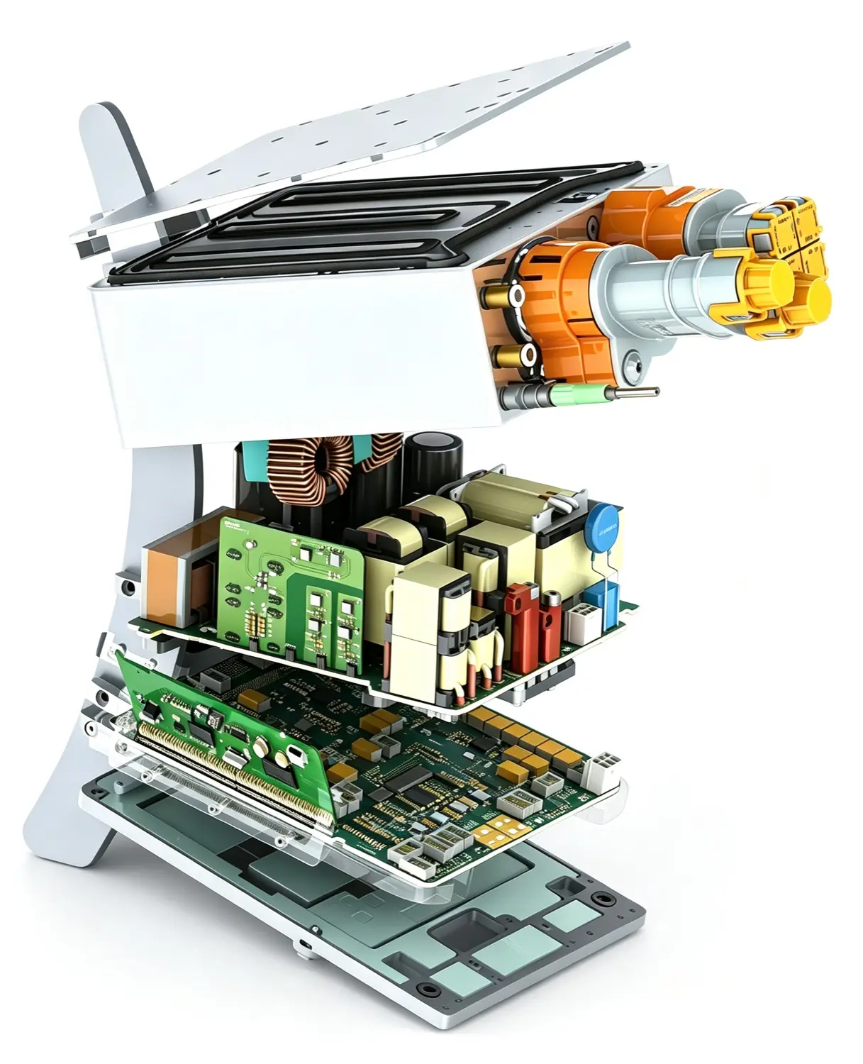
Gap fillers, potting and insulation for the charger's chip, magnetics, PCB and MOSFET positions.

\n
\n
\n
\n Exploded view of an on-board charger with power board, magnetic transformer, capacitors and connectors\n
OBC — chip, magnetics and power stage
\n
\n
\n
    \n
  • \n
    Chip
    \n
    2K Gap FillerUltrasoft Thermal PadThermal Grease
    \n
  • \n
  • \n
    Magnetic Core Transformer & Capacitors
    \n
    Potting CompoundCompressed Thermal Pad
    \n
  • \n
  • \n
    PCB & Heatsink
    \n
    2K Gap FillerReinforced Thermal Pad
    \n
  • \n
  • \n
    MOSFET
    \n
    Insulation SilpadThermal Grease
    \n
  • \n
\n

Insulation and thermal conduction are specified together — the silpad has to hold dielectric strength at the assembly pressure.

\n
\n
\n
\n
\n
\n
\n
\n
\n Material Platform\n

Six Families Cover Every Interface

\n
\n

One supplier and one qualification route — from soft thermal pads to structural adhesives and fire-protective coatings.

\n
\n
\n
\n 01\n

Thermal Pads

\n
  • Soft and ultrasoft gap pad
  • Reinforced and compressed pad
  • Defined thickness, clean assembly
\n View thermal pads \n
\n
\n 02\n

Gap Fillers & Potting

\n
  • 2K thermal gap filler
  • Silicone / epoxy / PU potting
  • Fills uneven gaps at low stress
\n Material families \n
\n
\n 03\n

Structural & Thermal Adhesives

\n
  • Epoxy and PU structural
  • Anaerobic thread lockers
  • Thermally conductive bonding
\n Material families \n
\n
\n 04\n

Insulation & Dielectric

\n
  • PC sheets 0.175–0.5 mm
  • High-performance silpad
  • One-side PSA available
\n Material families \n
\n
\n 05\n

Coatings & Cell Performance

\n
  • Dielectric coating
  • Conductive electrode coating
  • Fire-protective coating
\n Material families \n
\n
\n 06\n

Sealing & Casing

\n
  • Gasketing and FIPG
  • Impregnation solutions
  • Metal pretreatment
\n Material families \n
\n
\n
\n
\n
\n
\n
\n
\n Program Support\n

From Interface Review to Mass Production

\n
\n

The material is only one part of the answer — format, conversion and validation decide whether it works on the line.

\n
\n
\n
\n 01\n
\n Material selection\n
\n Interface review\n Gap & pressure\n Thermal target\n
\n
\n
\n
\n 02\n
\n Prototype\n
\n Die-cut samples\n Dispensing trial\n PSA backing\n
\n
\n
\n
\n 03\n
\n Validation\n
\n Thermal cycling\n Vibration\n Dielectric strength\n
\n
\n
\n
\n 04\n
\n Mass production\n
\n Batch traceability\n PPAP support\n Global logistics\n
\n
\n
\n
\n
\n
\n

Not sure which material fits your heat path?

Send the heat load, gap and environmental class — our application engineers will recommend the material and format for that position.

Talk to engineering